|
 |
INSTRUCTION MANUAL
|
 |
 |
Universal comfort controller for:
Mercedes C-Class (W203)
Mercedes E-Class (W211)
Mercedes S-Class (W220)
Mercedes ML-Class (W164)
Mercedes GL-Class (X164)
Mercedes R-Class (W251/V251)
v3.1
|
Further information and manuals for all products can be found on our web site
w w w . m o d s 4 c a r s . c o m
|
| |
We explicitly point out that all functions of this control unit should be used only while exercising caution and responsibility. We can NOT be held liable for any damage or injury caused by installing or using this product.
PLEASE READ THE COMPLETE MANUAL CAREFULLY BEFORE USING THIS PRODUCT. |
|
All functions of this module can be adjusted according to the user's needs:
Function 1 - Workshop/Diagnose mode. Behaves as if the module is not installed.
Function 2 - One-Touch windows up and down by remote.
Function 3 - Unlock doors automatically when key is pulled.
Function 4 - Chirp on lock (1 short beep) and optionally on unlock (2 short beeps).
Function 5 - HomeLight XL.
Function 6 - TVEnable.
Function 7 - Daytime Driving Lights.
Detailed function description (* = Factory Setting):
Function 1 - Product Enable - Workshop/Diagnose Mode ( 0=OFF / *1=ON )
When disabled, the module becomes completely inactive and behaves as if it was not installed. This is useful if you need to take the car to the dealer or garage for inspection or repairs.
Function 2 - Remote windows operation ( 0=OFF / *1=ON / 2=No Hazards / 3=AUTO )
This function allows window operation with the original remote using the RF signal. This works on cars with and without the IR receiver and allows for a much greater range than the close range IR solution.
Tap UNLOCK on the remote 2x (in 1 sec intervals) to open all windows.
Tap UNLOCK on the remote 3x (in 1 sec intervals) to open the sunroof.
Tap LOCK on the remote 2x (in 1 sec intervals) to close all windows.
Tap LOCK on the remote 3x (in 1 sec intervals) to close the sunroof.
In each case, tapping the same button again within 2 seconds of operation will open/close everything.
Tapping the opposite button will interrupt the current operation immediately.
Setting 2 disables the hazard lights during remote operation.
Setting 3 enables AUTO-CLOSE: Every time the car is locked by remote, all windows and sunroof close automatically.
WARNING: USE THIS FUNCTION AND PARTICULARLY SETTING 3 WITH EXTRA CAUTION! MAKE SURE THAT EVERYTHING IS CLEAR BEFORE LOCKING THE VEHICLE! NEVER LEAVE THIS FUNCTION ENABLED WHEN GIVING THE KEY TO SOMEONE ELSE! WE CAN UNDER NO CIRCUMSTANCES BE HELD LIABLE FOR ANY CONSEQUENCES OF USING THIS (OR ANY OTHER) FEATURE OF THIS MODULE!
Function 3 - Automatic power locks ( 0=OFF / 1=LOCK ONLY / *2=KEY OUT / 3=IGNITION OFF )
This function can be set to automatically lock the doors when driving (setting 1) and additionally unlock the doors automatically, when either the key is pulled from the ignition lock (setting 2) or when the ignition is turned off (setting 3).
Function 4 - Chirp Sound on lock/unlock ( *0=OFF / 1=HORN L / 2=HORN L+U / 3=SIREN L / 4=SIREN L+U )

|
This function can be set to either chirp once when locking the car (setting 1) or additionally chirp twice when unlocking (setting 2). Setting 1 and 2 use the regular horn, setting 3 and 4 use the alarm siren (requires factory alarm with red "panic" button on the remote fob).
To enable the horn chirps, open the fuse box in the right corner of the engine compartment and reseat the fuse shown from position 43A, left slots (1) to position 43B, right slots (2). This change does not affect anything else.
|
|
|
Function 5 - HomeLight XL ( *0=OFF / 1=FOG / 2=DIPPED BEAM )
This function turns the headlights on for 30 sec., when the PANIC button on the remote is tapped briefly. To turn the headlights off manually, just tap the button again. Setting 1 activates the fog lights and setting 2 activates the regular dipped beams as the light source. Alternatively (when there is no PANIC button present), tap "UNLOCK" once with the car already unlocked or tap "LOCK" once with the car already locked.
Please note: On the S-Class both enabled settings (1 and 2) activate all yellow turn signal lights, since the fog and headlights can not be controlled remotely.
Function 6 - TVEnable ( *0=OFF / 1=ON )
With this function enabled it is possible to play DVDs (if dvd-enabled COMAND system present) or watch TV (if TV enabled COMAND present) while driving. Usually the system prevents any multimedia operation while the car is moving. This feature allows the passenger(s) to enjoy multimedia content while travelling.
WARNING: NEVER DRIVE AND WATCH TV!!! THE TV FEATURE IS SOLELY INTENDED FOR PASSENGERS TO OPERATE AND WATCH THE SCREEN! ENABLING THIS FEATURE REQUIRES FULL RESPONSIBILITY AND IS DONE AT YOUR OWN RISK ONLY! WE CAN UNDER NO CIRCUMSTANCES BE HELD LIABLE FOR ANY CONSEQUENCES OF USING THIS (OR ANY OTHER) FEATURE OF THIS MODULE!
Function 7 - Daytime Driving Lights ( *0=OFF / 1=ON )
Enable this function to turn the headlights (low beams) on as soon as the engine is started. Some countries require the front lights to be permanently on.
WARNING: This function ONLY ACTIVATES THE FRONT LIGHTS !!! You have to make sure that you still turn the light switch if you drive at night, since this function will NOT activate any rear lights or dash board illumination!
InstallAID™ LED:
This module is equipped with our unique installation help and status indicator LED.
The LED signals a correct installation and shows the status of the module in a clear and easy to understand way.
LED OFF
Ignition OFF: CAN bus and module are in low-power standby mode. This is normal.
Ignition ON: Either power connection or CAN bus connection is interrupted. Troubleshooting: Check the two wire taps for 12V and ground as well as the CAN connectors. Also make sure the CAN polarity is correct.
LED permanently ON
Ignition OFF: Should not happen! CAN bus and module should enter standby mode after max. 1 min. The LED MUST turn off at some point.
Ignition ON: Module is connected to CAN and power, but not in line with the correct CAN plug. Troubleshooting: Starting with the first CAN plug, hook the module up to each one of the plugs until the LED shows a distince blinking pattern (1x per sec) max. 5 sec after turning the ignition on.
LED blinks
CAN Bus is active, the module is connected correctly and ready for use.
|
|
| Programming |
This module is equipped with an interactive setup menu to allow easy setting of the desired options.

|
All programming is done by using the steering wheel buttons (1,2,3) and the two green turn signal (indicator) arrows.
Functions are indicated by the left arrow (4) and their settings by the right arrow (5). Additionally, the main cluster display shows all functions and options in clear text (where available).
Navigation is done by pushing the up and down buttons on the left (2) or the phone pickup and hang-up buttons on the right (2) and settings changed by pushing the plus and minus buttons (3).
Each time either a new function is selected or a function's setting is changed, the blinker arrows will indicate the new status by first blinking the function (left arrow) and then the setting (right arrow).
On all SUV type cars (ML, GL, R), the functions have to be selected using the phone pickup/hang-up buttons only, since the UP/DOWN buttons are disabled and can not be used to control our setup menu.
|

|
To enter programming mode, first make sure the key is not in the ignition lock and all doors are unlocked. Insert the key into the ignition lock and turn it to accessory position.
To access the clear text setup, make sure the radio/command unit is turned OFF, then select the AUDIO screen using the steering wheel MENU buttons on the left.
Next, press and hold the phone hang-up button on the steering wheel until the left arrow blinks once to indicate function 1. Now let go of the button.
From this point on you can navigate through the options by either tapping the UP (next function) and DOWN (previous function) buttons or the phone pickup (next function) and phone hang-up (previous function) buttons.
Once the arrows are finished indicating the function and setting, change the setting by tapping PLUS or MINUS. The new settings are active immediately.
|
To end programming mode, remove the key from the ignition lock or turn the ignition on. End of programming mode is indicated by both arrows lighting up simultaneously.
Examples:
Function 2 (Remote) is enabled (setting 1): Left arrow blinks twice to indicate function 2, then right arrow blinks once to indicate that this function is set to setting 1 (ON).
Function 4 (Chirp) is set to OFF (setting 0): Left arrow blinks 4 times to indicate function 4, then right arrow does not blink. This indicates that the function is set to setting 0 (OFF).
When the module is ENABLED (active), function 1 will be indicated as ON (1x left arrow followed by 1x right arrow). The DISABLED (module deactivated) mode will be indicated as 1x left arrow only.
In case the left arrow is finished blinking and the right arrow does not light up at all, the appropriate function is set to setting 0 / OFF and hence disabled.
|
|
| Installation - Steps 1-3 |

| 1. Move the seat all the way back first, then firmly grab under the plastic cover with both hands (on the inside) and pull up hard. The cover is held in place by the brackets marked with the red circles. |

| 2. Check the circled spots for T20 torx or philips head screws that hold the side panel in place. If present, remove any screw covers before unscrewing. Take the side panel out by pushing it outward (left) and down. Pay attention to how it interconnects with the other parts so you can re-install it correctly later. |

| 3. C/E/S Class only: Pull up the carpet all the way along the left side. Beneath it you will find a black wire harness box. Its cover is held in place by plastic tabs. Unclip the tabs and pull the plastic cover up. |
|
|
| Installation - Steps 4-6 |

| 4. S Class: Remove left plastic bracket of driver's seat rail, then lift up the carpet all the way until you see a plastic cover with a black wire clipped into it. This is the part that needs to be lifted up. Underneath is the CAN terminal block. It is pretty well hidden in the leftmost corner. Use a flashlight. |

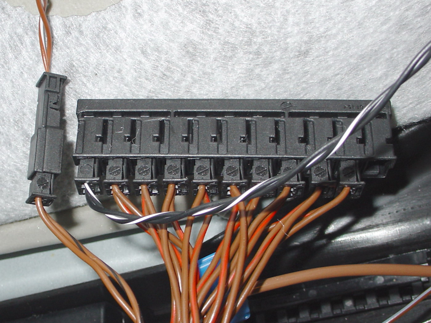
| 5. The goal is to locate and work on the CAN BUS terminal block with the brown wires connected to it. It needs to be removed from its bracket. You may need to carefully pry it out with a screwdriver, as shown. Just stick the screwdriver between the bracket and the terminal block while pulling up on the terminal block. |

| 6. On all SUV type cars (ML/GL/R Class) the CAN bus connector is to be found behind the side panel on the driver's side. Lift up the doorsill as mentioned above, then remove the side panel by just unsnapping it. Locate the CAN terminal block (1) with all the brown and brown/red wires connected to it and remove it from its bracket. On some models it may happen, that there is no CAN on the driver's side. If that is the case, check the passenger's side. |
|
|
| Installation - Steps 7-9 |

| 7. Attaching the wire taps:
S Class: RED wire (or RED wire with PURPLE STRIPE, if present) (+12V) and BROWN wire (GROUND).
SUVs (ML/GL/R Class): RED wire (+12V) and BROWN wire (GROUND).
These taps are removable and only leave minimal traces, which usually stay unnoticed. |

| 8. Attaching the wire taps:
C/E Class: RED wire with WHITE STRIPE (+12V) and BROWN wire (GROUND), both going to a black or blue connector. |

| 9. PLEASE NOTE: The plastic bracket must be removed, before any plugs can be pulled out. It is held in place by two tabs on the sides. Push the tabs outward while simultaneously pulling the cover piece upward or stick a screwdriver between the bracket and the terminal block and carefully pry it off. It is a bit tricky to get off, so please be patient and don't use brute force. With the cover gone, the plugs can be removed. The following step explains in detail, how to find the correct plug which needs to be removed and replaced by the one from the module.
Connect the brown ground wire and the red +12V wire before proceeding. |
|
|
| Installation - Steps 10-12 |

| 10. Because of the module's universal compatibility and different pin-assignments used by Mercedes Benz, all modules are shipped with just the blank pins on the ends of the wiring harness, along with the needed plastic caps. Insert the pins on the module wire harness into the supplied plastic caps according to your car model. The positions on the plastic caps are clearly marked with "1" and "2". The long thin pins go into the bigger one of the two caps. Top half (C, E, ML, GL, R Class) RED wires go in position 1, BLACK wires go in position 2. Bottom half (S Class) BLACK wires go in position 1, RED wires go in position 2. Push the pins into the correct position hole in the cap, making sure it locks into place with an audible "click". After inserting all pins, push the plastic latch on the side of the plastic caps in. It also locks into place with an audible "click". Now the plugs are ready for the next step. |
| 11. Start from the far left on the can bus terminal block removing the plug from the socket.Replace the plug just pulled with the one from the module and insert the plug into the module's socket, completing the electrical circuit with the module "in between". Double-check that the original BROWN/RED wire meets up with the module's RED wire and the original BROWN wire meets up with the module's BLACK wire. Tap the UNLOCK button on the remote once and watch the STATUS LED on the module.
LED does not light up at all: No power, probably one of the power taps not making proper contact - Check and retry.
LED stays on solid: Power OK, but wrong bus connection. Use next plug and retry.
LED flashes on/off about 1x/sec.: Everything is connected correctly. Done.
|

| 12. ALL MODELS:
Place the module inside the harness box. Close the lid and make sure all tabs snap back in place. Replace carpet and side panel. Make sure you snap the side panel in place correctly, as there may be tabs that interconnect with other plastic parts of the dash or the hood release lever cover parts. Replace screws and plastic cover. Installation is complete. |
|